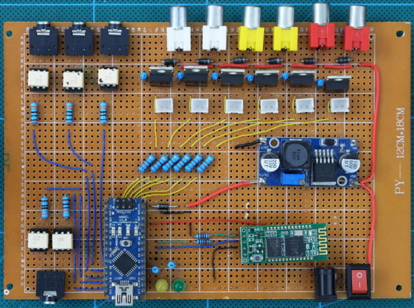
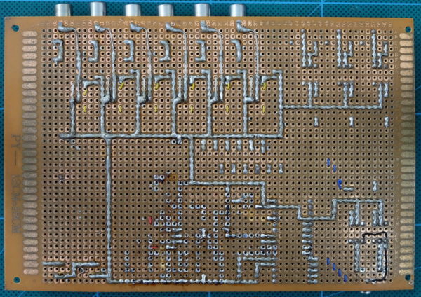
If you want to build a more permanent device then proto-board is a good option. Unfortunately I do not have a step by step guide but hopefully, between the circuit diagram and the below photos it should be fairly easy to figure things out.
You can find the circuit diagram here. The circuit diagram page also includes details about some of the components.
I tried to lay out the board in a logical fashion which I used as a stepping stone to creating a proper PCB. This included positioning the sockets so that the wires didn’t overlap each other.
I always intended to put this in to a project box but never found a suitable case. With hindsight I should have made it smaller and used panel mounted connectors rather than PCB mounted ones. Or, better still, found a case first.
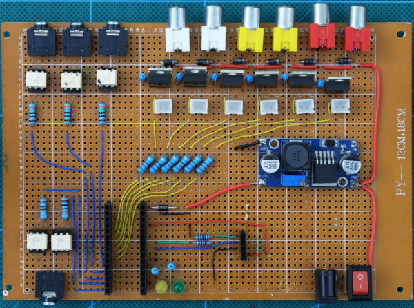
Here is the board without the Arduino and the Bluetooth module
And here is the board with the connections overlaid.
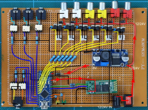
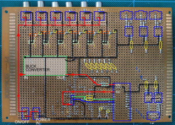
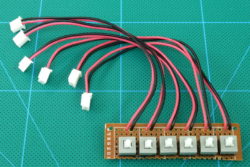
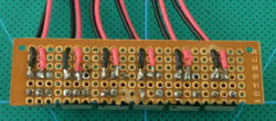
The prototype includes sockets to attach manual drain switches. These can be removed and are not included on the final PCB.

The RCA sockets and power jack socket is not proto-board friendly and I had to drill larger holes to accommodate the large pins.
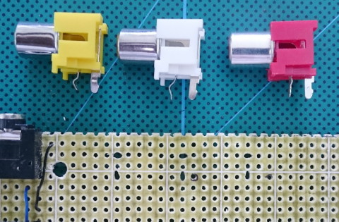
Image taken from dropController V2.
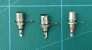
Panel mount RCA sockets
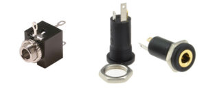
Panel mount 3.5mm sockets
The benefit of using panel mount sockets is you only need to get the hole size correct. The position does not need to be 100% accurate. This makes construction a lot easier.
Here is a version with all the ports on one side.
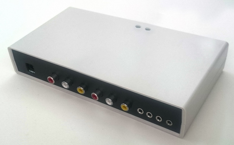
Getting the holes in the back panel lined up took many revisions and it would have been better to use panel mounted sockets rather than PCB mounted ones.
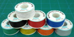
Wire
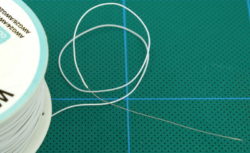
For the power lines I used 24awg wire. For the rest of the circuit I used single core wire-wrap wire. Single core wire-wrap wire is ideal for use with protoboarding.
When soldering long lines I use lengths of stripped wire. This makes creating long neat tracks fairly easy.
Normally I fully solder the wire in place but sometimes I get lazy and don’t.
